The season is here for summer monsoon storms — and ensuing flash flooding that in Arizona can crash the landscape with little warning – to potentially blanket much of the state.
Designed with various features for managing storm water, the 336-mile Central Arizona Project (CAP) canal uses protective infrastructure against potentially harmful impacts to its canal system and water quality thanks to engineering that assist the natural drainage layout.
Original flood protection design
The CAP was originally designed by the Bureau of Reclamation (Reclamation). The canal alignment traverses numerous natural drainage-ways in its mostly south-easterly flow direction across central Arizona.
Surface water runoff is intercepted by embankments and conveyed under, or over, the canal with cross drainage structures. These structures include inverted siphons, flumes, underchutes (box culverts), pipes and overchutes. There are also flood protection works that were designed into the Waddell Dam and Waddell Pump-Generating Plant. There are approximately 288 cross-drainage structures along the entire length of canal and about 170 miles of collective and protective dikes.
To determine the proper size of each feature, Reclamation used precipitation models and watershed delineations to calculate the volume of water that would be generated by the 100-year, 6-hour storm event. This storm size was typically used to calculate the volume of water that needed to pass across the CAP at numerous locations along the system. Storm events that are larger than the design storms used originally by Reclamation can occasionally lead to some level of damage to the CAP system of embankment dikes and cross drainage structures.
Now we’ll take a look at CAP’s five primary flood protection features.
1. Standard overchute
These overchutes, either a steel pipe or open-top concrete box, cross over the canal and simply relay water to the other side. These were typically installed at a point with a natural wash and where the canal is in a cut section or below the surrounding ground.
An open-top concrete box overchute on the CAP canal carries flood water to a wash.
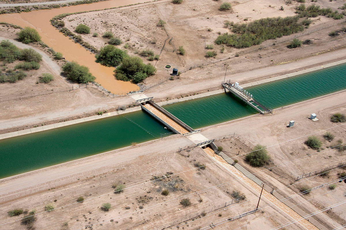
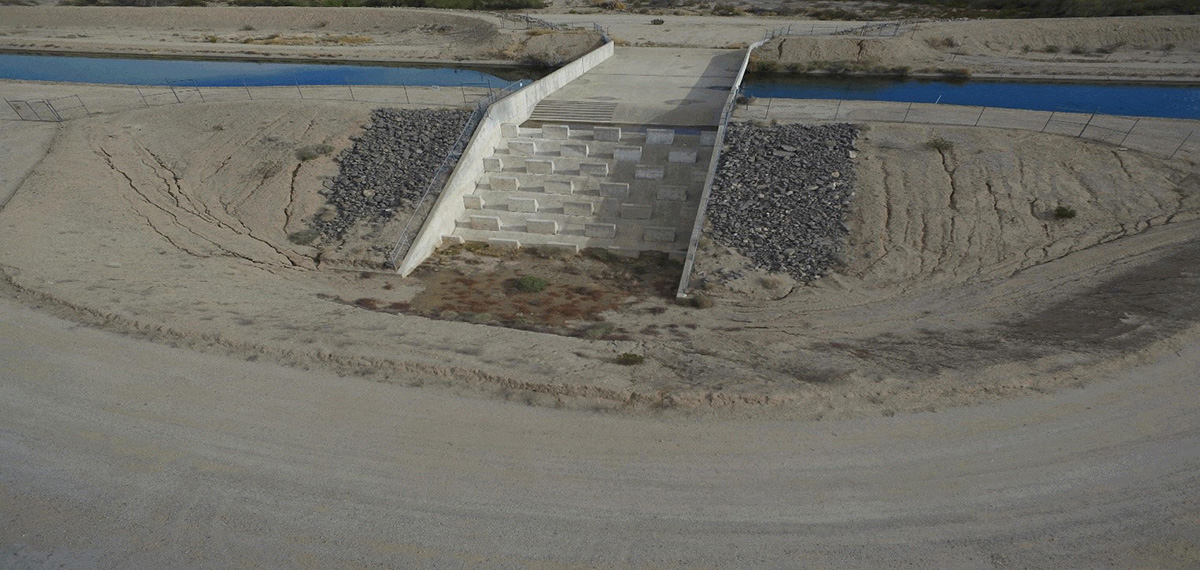
2. Concrete flume overchute
Engineered to carry higher volumes of water across the canal, a larger flume can be at least 80 feet wide at the top, carrying water to an area or wash on the downstream side. Two concrete flume overhcutes at Skunk Creek in Maricopa County are 156 and 244 feet wide, respectively. The baffle blocks seen at the outlet (pictured above) are energy dissipators that slow the flow of water and help to reduce soil erosion.
A concrete flume overchute outlet
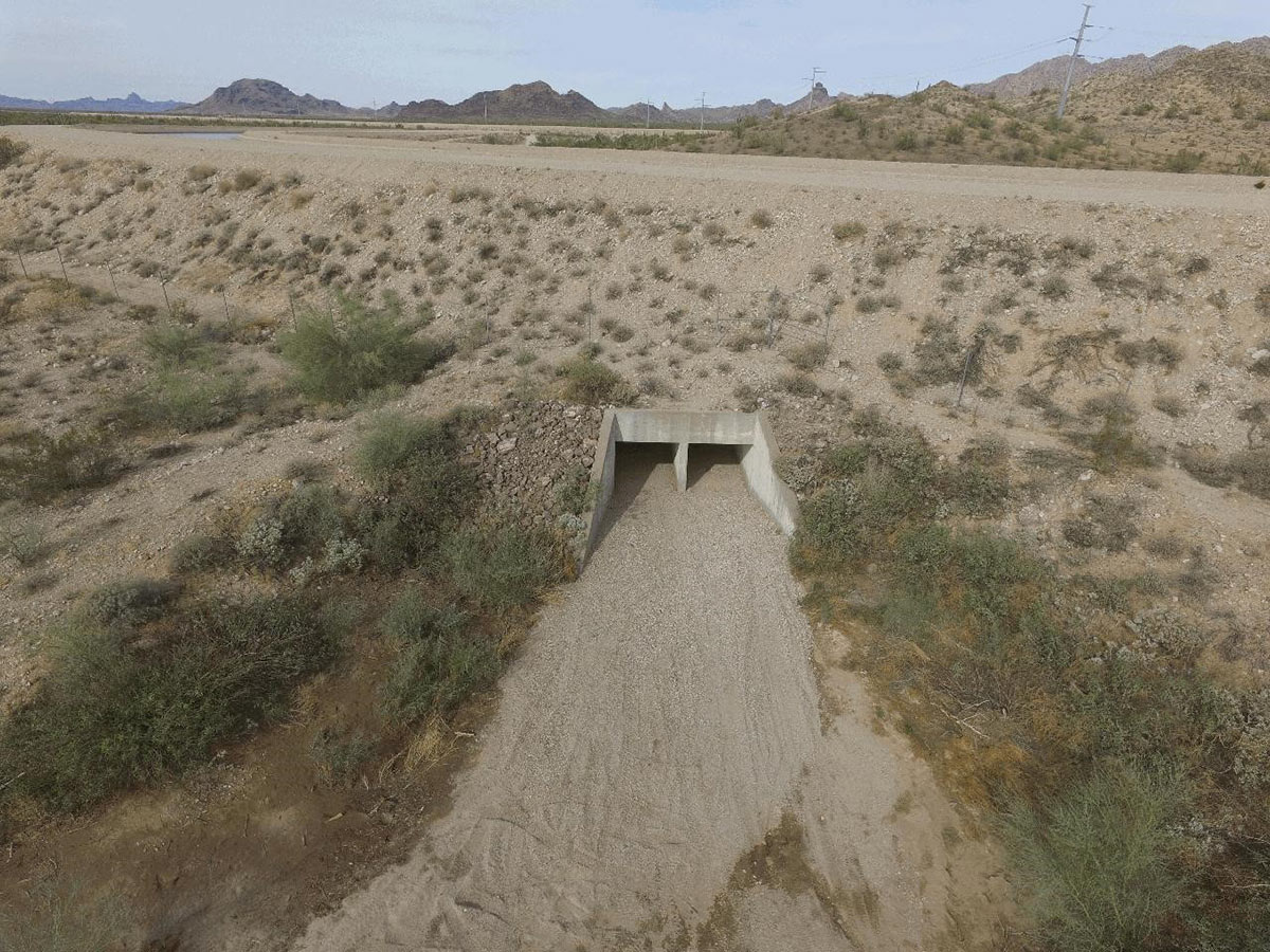
3. Underchutes
An underchute occurs in areas where the canal is elevated. This could be just “downstream” of a pumping plant where there’s a sharp elevation gain and a plant has lifted water uphill — 15 pumping plants carry water nearly 3,000 feet uphill across the course of the system. Or, an underchute could be located where the canal is elevated above the original ground surface to maintain the right hydraulic slope. Had the canal not been present, natural drainage of stormwater would have passed through such an area.
The outlet of a concrete box culvert underchute is capable of delivering water beneath the CAP canal.
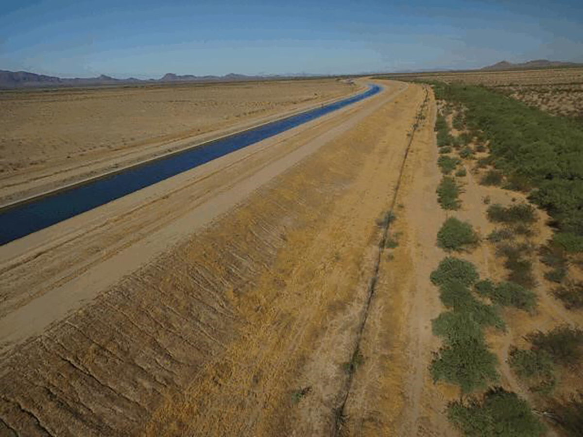
4. Berms and embankments
As flood water naturally flows to a lower point, berms and embankments, typically located on the north and east sides of the canal, assist this topographical layout by collecting and directing water to these low points where there will likely be a natural wash as well as a feature to carry water over the canal typically referred to as an overchute.
As with all these flood protecting features, the strategy is to deliver the water across the canal and back into the natural wash channel where it can continue down its natural flow path.
An upstream embankment on the CAP canal
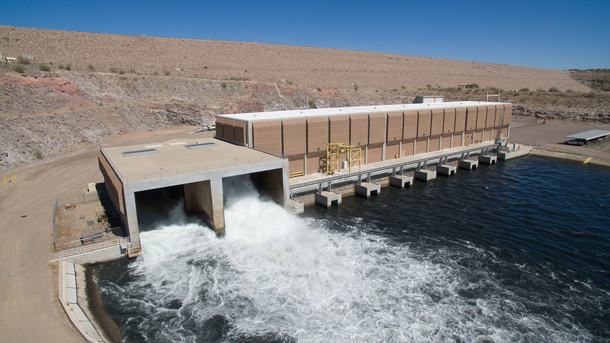
5. New Waddell Dam bypass valves
Lake Pleasant is CAP’s storage reservoir, providing flexibility to balance Colorado River water supply diversions and customer deliveries, and maintaining the CAP system and energy costs.
Among the features capable of rapidly lowering Lake Pleasant’s elevation in the event of flooding are two mammoth bypass valves on the southern shore of the reservoir that are especially effective at quickly releasing large volumes of water into the Waddell Canal and then the mainline canal if downstream canal capacity is available. If it isn’t, excess water can be directed into a wasteway and into the Lower Lake at Waddell, before finally passing over the Maricopa Water District Dam and into the Agua Fria River. This is known as “spilling water” and is a last resort. Every effort is made by CAP’s Water Operations Department to use Lake Pleasant releases through Waddell’s generating units to generate hydro-electric power and make available all water to downstream CAP water users or CAP’s water recharge program.
Two 132-inch fixed cone bypass valves on the southern shore of Lake Pleasant bypass the Waddell Pump/Generating Plant.
For the infrastructure, all these protective measures mean preventing erosion and other structural damage using planned, controlled releases.
For the water quality, these features help keep potentially harmful sediment and other debris from entering the CAP Colorado River water that eventually flows through turnouts and into treatment plants. CAP also monitors water quality and provides water quality data as an additional service to water users.
System protection planning
Currently, CAP is working to:
Monitor weather events and any new information that may be available for precipitation models that need to be updated due to trends or changes to climate.
Partner with local flood control districts and regional hydrologic experts. This plays a key role in CAP’s effort to continually evaluate the suitability of CAP’s drainage and flood control features.
Make recommendations and changes to improve or modify existing infrastructure based on hydrologic studies and financial risk analyses. This helps ensure the long-term reliability and protection of the CAP system.
Monsoon storms have arrived, but CAP water users – and the end users of that water – can count on this precisely-engineered collection of CAP infrastructure to help protect the reliability of the Colorado River system.
KRA: Project Reliability
Providing reliable and cost-effective operations, maintenance, and replacement of CAP infrastructure and technology assets